[ TECHNICAL DOCUMENTATION ]
Sparrow Payload Interface
The Blackwing Space Sparrow 1U platform is our compact, commercially-available nanosatellite solution designed to make space accessible for startups, universities, and research institutions. As the smallest platform in the Blackwing Space bird family, Sparrow delivers a cost-effective pathway to orbit while maintaining the modularity and performance standards essential for modern space missions.
This page defines the mechanical, electrical, and data interfaces between the Sparrow 1U platform and customer-supplied payload, ensuring seamless integration of mission-specific hardware into a proven, American-made platform ready for rapid deployment.
Payload Size, Weight, and Power
| Parameter | Sparrow 1U Capability |
|---|---|
| Available Payload Mass | 0.5 kg (1U), 1 kg (1U XL) |
| Available Payload Volume | 0.3U |
| Available Payload Power | 1-10W OAP |
Payload Mechanical Interface
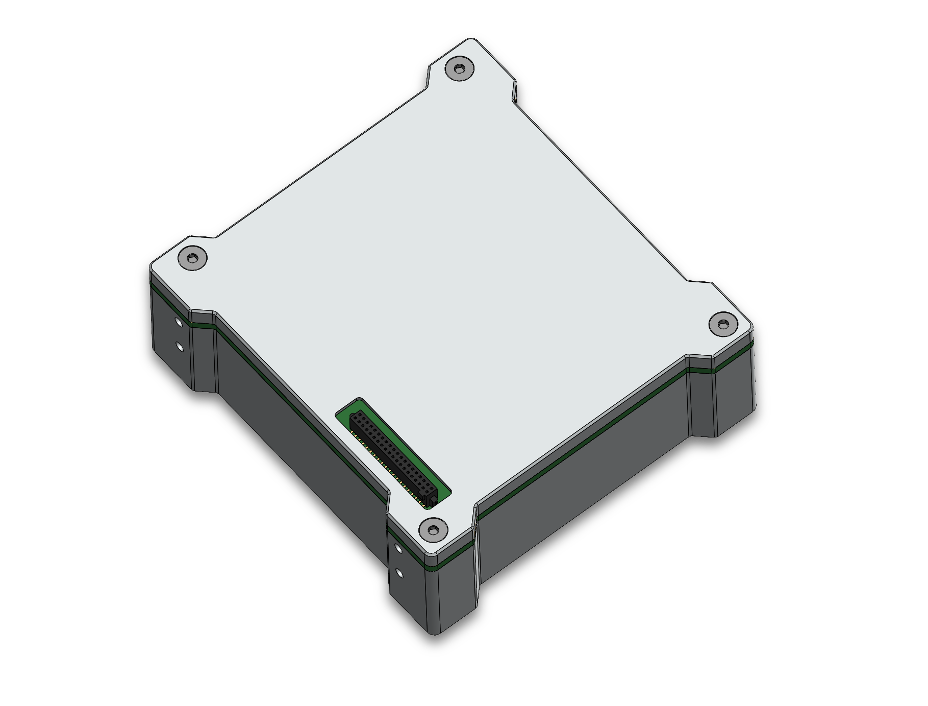
The Sparrow payload module provides a standardized 0.3U mounting envelope with defined metric fastener locations and alignment features to support rapid payload integration. The payload module plugs directly into the Sparrow platform avionics enclosure via a single Samtec board-to-board connector, and then the mated platform avionics-payload assembly is integrated into the Sparrow 1U chassis. A STEP template for the Sparrow payload module is provided to validate fit, alignment, and clearances prior to fabrication.
Sparrow Integrated Assembly
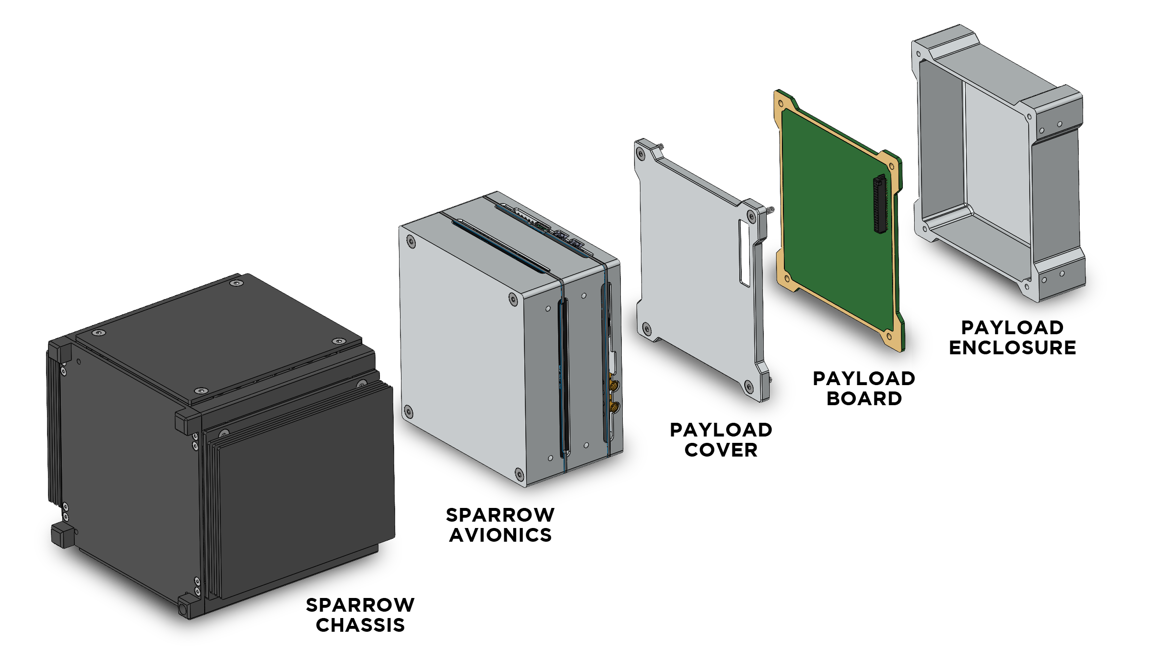
Sparrow Payload Module
Templates
GD&T Drawing
- Download - Payload Module PDF
- Download - Payload Cover (Top) PDF
- Download - Payload Enclosure (Bottom) PDF
Payload Electrical Interface
All payload power, digital, and analog signals to and from the Sparrow 1U platform are routed through a single 40-pin board-to-board connector that simplifies payload-platform electromechanical integration, testing, and flight operations.
This payload connector specification defines the physical mating interface only. Signal assignments and electrical behavior are defined explicitly on this page and do not follow any standardized bus such as ISA or PCIe.
Power Interface
The Sparrow 1U platform provides three payload power rails via the payload connector. Each rail can be independently enabled or disabled by the Sparrow platform for sequencing, fault protection, and power cycling. Payloads must implement over-current protection on all power inputs used by payload hardware, and must not back-drive any power rail during operation.
| Power Rail | Nominal Voltage | Regulation | Max Payload Current |
|---|---|---|---|
| 3V3 | 3.3V | Regulated | 1A |
| 5V | 5.0V | Regulated | 1A |
| VBATT | 7.0-8.4V, nominally 7.2-7.4V | Unregulated | 2A |
Digital Interface
The following digital interfaces are available on the Sparrow 1U payload connector to provide flexibility for payload developers. The payload can communicate with the platform avionics using one or multiple of these bidirectional communications protocols.
| Interface | Direction | Logic Level | Notes |
|---|---|---|---|
| I2C | Bidirectional | 3.3V | Clock and data provided |
| SPI | Bidirectional | 3.3V | Driven by Rook motherboard |
| UART | Bidirectional | 3.3V | Asynchronous with optional flow control |
| GPIO | Configurable | 3.3V | Spare and customer-defined |
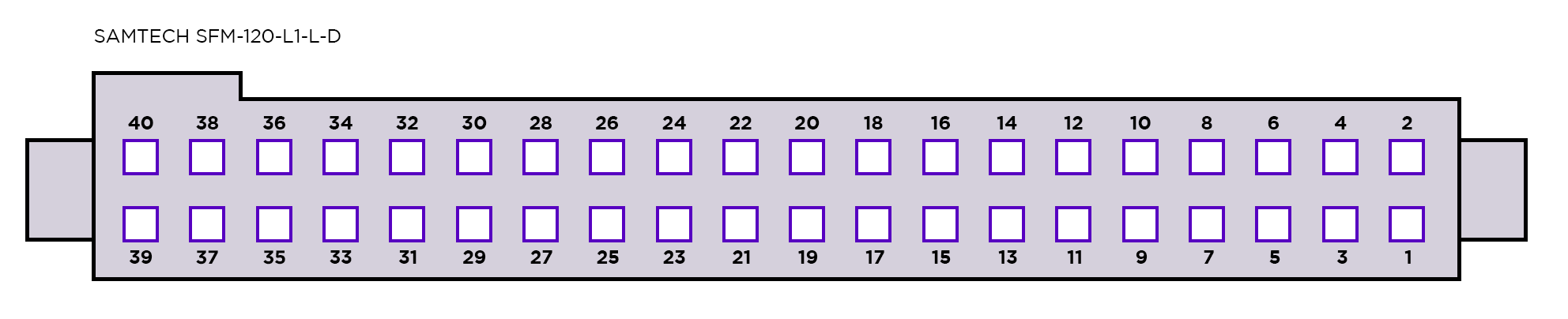
Payload Connector
Specifications
| Parameter | Value |
|---|---|
| Payload Connector | Samtec SFM-120-01-L-D |
| Platform Connector | Samtec TFM-120-31-L-D |
| Total Pins | 40 |
| Pitch | 1.27 mm |
| Logic Level | 3.3V nominal for digital I/O |
Pinout
| Pin | Function | Net Name | Notes |
|---|---|---|---|
| 1 | VBATT | VBATT | Battery power rail (1 of 4) |
| 2 | VBATT | VBATT | Battery power rail (2 of 4) |
| 3 | VBATT | VBATT | Battery power rail (3 of 4) |
| 4 | VBATT | VBATT | Battery power rail (4 of 4) |
| 5 | I2C_SCL | PA19 | I2C clock |
| 6 | GND | GND | Ground |
| 7 | I2C_SDA | PA22 | I2C data |
| 8 | GND | GND | Ground |
| 9 | SPI_MOSI | PA12 | Defined by Rook motherboard |
| 10 | GND | GND | Ground |
| 11 | SPI_MISO | PA14 | Defined by Rook motherboard |
| 12 | GND | GND | Ground |
| 13 | SPI_SCK | PA13 | Defined by Rook motherboard |
| 14 | GND | GND | Ground |
| 15 | SPI_CS0 | PB17 | GPIO chip select |
| 16 | GND | GND | Ground |
| 17 | UART_TX | PA20 | UART to payload |
| 18 | GND | GND | Ground |
| 19 | UART_RX | PA21 | UART from payload |
| 20 | GND | GND | Ground |
| 21 | UART_CTS | PB16 | Flow control from payload |
| 22 | GND | GND | Ground |
| 23 | UART_RTS | PB23 | Flow control to payload |
| 24 | GND | GND | Ground |
| 25 | 3.3V | 3V3 | 3.3V power rail (1 of 4) |
| 26 | 3.3V | 3V3 | 3.3V power rail (2 of 4) |
| 27 | 3.3V | 3V3 | 3.3V power rail (3 of 4) |
| 28 | 3.3V | 3V3 | 3.3V power rail (4 of 4) |
| 29 | SPARE_GPIO1 | PA17 | Spare GPIO |
| 30 | GND | GND | Ground |
| 31 | SPARE_GPIO2 | PB16 | Spare GPIO |
| 32 | GND | GND | Ground |
| 33 | SPARE_01 | NC | Not connected |
| 34 | SPARE_02 | NC | Not connected |
| 35 | SPARE_03 | NC | Not connected |
| 36 | SPARE_04 | NC | Not connected |
| 37 | 5V | 5V | 5V power rail (1 of 4) |
| 38 | 5V | 5V | 5V power rail (2 of 4) |
| 39 | 5V | 5V | 5V power rail (3 of 4) |
| 40 | 5V | 5V | 5V power rail (4 of 4) |
Payload Software Interface
Coming Soon
Last Updated: May 28, 2026
Version: 0.2
Need Help?: For detailed mission-specific interface questions, reach out to us.